How to use solidworks miter flange solidworks sheet metal tutorial 2 sheet metal miter flange is also like edge flange helps to add one or more flanges on base flange sheet metal part.
Solidworks sheet metal gap distance.
Select material inside or bend outside to specify where to add the material.
Like show 0 likes 0.
Only available if a sheet metal gauge table has been selected for the part select or clear.
Now let s use solidworks to create a sheet metal transition.
1 solidworks tutorial for be.
However in some circumstances when the design requires certain types of geometry you can use non sheet metal feature tools then insert bends or convert the part to sheet metal.
Close multiple corners simultaneously by selecting the faces for all of the corners that you want to close.
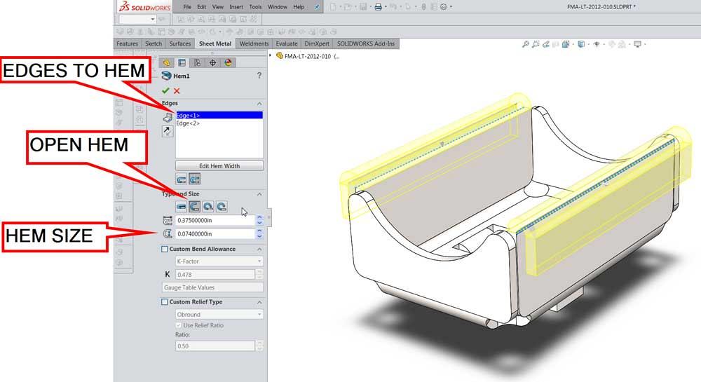
In an open sheet metal part click hem on the sheet metal toolbar or click insert sheet metal hem.
Question asked by 1 f44ghu on nov 4 2008 latest reply on nov 7 2008 by angela crawford.
You might also like.
In the propertymanager under edges.
The rectangular geometry on the right side of the sketch is used to create and center a gap in the sketch geometry.
Finish sketch and exit sketch.
Miter flange is slightly different from edge flange because it needs a sketch profile of lines or arcs.
We will learn sheet metal basic features like base flange edge flange sketched bend and extruded cut in solidworks sheet metal.
Apply a closed corner to flanges with bends other than 90.
Start a new inch part and create a new sketch on the front plane.
Click edit hem width to edit the sketch of the profile.
If so where is this located.
How to implement these formulae in solidworks so they are smart models.
The selected edges appear in edges.
Adjust the gap distance.
Is there a default location for the gap distance measurment.
In the graphics area select the edges where you want to add a hem.
Constrain the geometry and dimension as shown.
Im creating editing our sheetmetal templates and have a formula for all the sheet metal gages for this gap distance and.
Set a value when use default radius and use gauge table are cleared.
There are specific sheet metal features you can use to create sheet metal bodies quickly.
The closed corner feature adds material between sheet metal features and includes the following capabilities.
Sheet metal gap distance.