Solidworks Sheet Metal Large Radius

Solidworks Sheet Metal Normal Cuts And Simplify Bends Youtube

Solidworks Sketched Bend Youtube
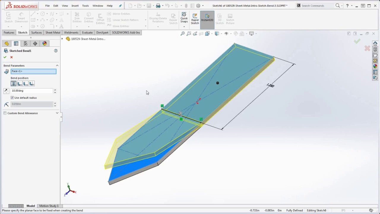
23 Solidworks How To Bend A Part Using The Sketch Bend Feature Intro To Solidworks Sheet Metal Youtube
Sheet Metal Success In Solidworks Engineers Rule

How To Create Sketched Bends Solidworks Tutorials Sheet Metal Youtube

Solidworks Sheet Metal Lofted Bend Youtube Sheet Metal Drawing Solidworks Sheet Metal

If a sheet metal manufacturer does not own a press brake tooling to achieve a large bend radius.
Solidworks sheet metal large radius.

Build Sheet Metal Assemblies The Easy Way

Solidworks Tutorial Corner Treatment Sheet Metal Tutorial Youtube

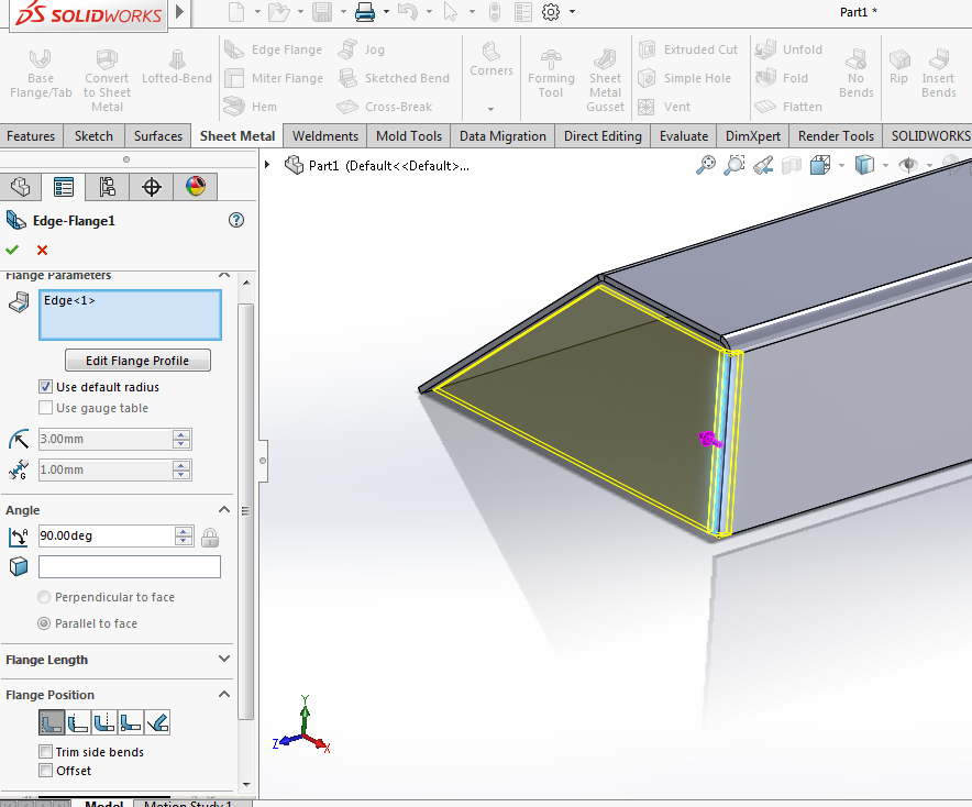
Solidworks Complex Sheet Metal Ege Flanges Youtube

Optimize Sheet Metal Fabrication Process By Designing Parts In Solidworks Sheetmetal Fabricationdrawings S Sheet Metal Fabrication Sheet Metal Metal Design
Source : pinterest.com
