To edit the default bend radius bend allowance or bend deduction or default relief type.
Solidworks sheet metal with different bend radius.
Add another sheet metal feature to the part.
We can also ensure that an appropriate sheet metal bend radius is utilized in the design process and that this bend radius can be achieved in the manufacturing processes.
By utilizing a solidworks sheet metal gauge table we can save time by eliminating the step of looking up sheet metal gauge values based on different materials.
Solidworks 3d allows you to quickly create sheet metal part designs using a simple design process saving you time and development costs thanks to specific sheet metal features.
Under sheet metal gauges select use gauge table and select a table.
In the featuremanager design tree right click sheet metal and click edit feature.
We can use these features to create sheet metal designs with several different methods.
To apply a bend radius value different from the gauge table value.
In the base flange propertymanager under sheet metal gauges select use gauge table and then select a table.
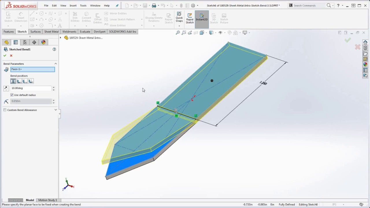
Select the fixed face on the model.
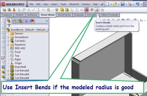
Click insert bends or click insert sheet metal bends.
Unfolded sheet metal before correction.
We will focus on the flange method where a sheet metal part is created in the formed state using specialized sheet metal features.
Look at part tree.
The name of the face is displayed in the fixed face or edge box.
Miter flange lofted bend corner controls sheet metal gusset and rip are all very common tools that can make life easier for the designer.
A quick tour and introduction using the solidworks sheet metal sketch bend feature.
In the propertymanager under bend parameters.
Your simple sheetmetal bend is ready.
Folded sheet metal with bottom added after correction.
Solidworks how to create a simple sheet metal part in solidworks.
Click sheetmetal insert bends click flat face as reference when it flatten.
Create a base flange and in the propertymanager under sheet metal gauges select use gauge table and then select a table.
In the new feature s propertymanager clear use default radius and select use gauge table.
To view this part in flatten form click sheetmetal flatten.
Select another value for the bend radius.
Set bend radius to 0 03in and k factor 0 5 and ok.
The fixed face remains in place when the part is flattened.